
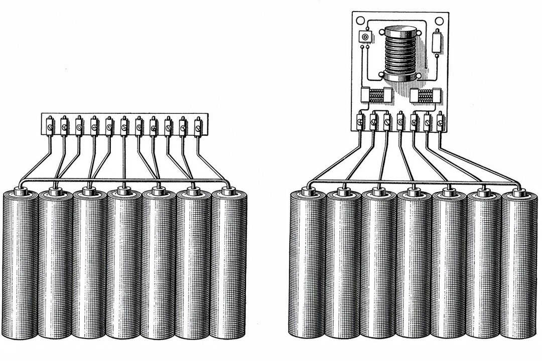
Kurzantwort: Passiver Ausgleich lässt die höheren Zellen in einer Serienschaltung über einen Widerstand auf das Niveau der niedrigsten Zelle absinken und wirkt nur während des Ladevorgangs. Aktiver Ausgleich verschiebt Ladung zwischen den Zellen, statt sie zu verbrennen, über eine von drei Schaltungstopologien, und kann während des Ladens, Entladens oder im Ruhezustand wirken. Keine der beiden Methoden ist automatisch die richtige Wahl: Die Entscheidung hängt vom Lastzyklus, dem Zielwert für die Zyklenzahl und davon ab, wie viel zusätzliche Kosten, Gewicht und Komplexität die Anwendung verträgt.
Ein paar Millivolt Ungleichgewicht pro Zelle klingen nach wenig. Bleibt dies unkorrigiert, summiert es sich Zyklus für Zyklus durch den Effekt der schwächsten Zelle und zeigt sich Monate später als ein Pack, das das Lebensdauerende erreicht, während die meisten seiner Zellen noch echte Kapazität übrig haben. Die Ausgleichsmethode, mit der ein BMS dieses Ungleichgewicht korrigiert, ist eine echte technische Abwägung, kein Häkchen auf einem Datenblatt.
Wird dies in die eine oder andere Richtung falsch spezifiziert, kostet es Sie. Wer aktiven Ausgleich in eine Anwendung mit niedrigem Lastzyklus spezifiziert, zahlt für Schalter, Magnetik und Leiterplattenfläche, die eine passive Schaltung und gute Zellsortierung ebenso hätten leisten können. Wer nur passiven Ausgleich in eine Anwendung mit hoher Zyklenzahl und engen Toleranzen spezifiziert, bei der das Pack nicht schnell genug korrigieren kann, erlebt einen früheren Kapazitätsverlust als im Datenblatt versprochen.
Warum wenige Millivolt Ungleichgewicht die Pack-Lebensdauer verkürzen
Zellen in einer Serienschaltung führen alle denselben Strom. Wenn eine Zelle in einem 6S- oder 12S-Pack etwas geringere Kapazität oder höheren Innenwiderstand als die übrigen hat, erreicht sie zuerst ihre Spannungs- oder Ladezustandsgrenze, an beiden Enden. Das Laden muss stoppen, sobald diese eine Zelle ihre Obergrenze erreicht, selbst wenn jede andere Zelle noch Spielraum hat. Das Entladen muss stoppen, sobald dieselbe Zelle ihre Untergrenze erreicht, selbst wenn jede andere Zelle noch Energie hat.
Das Ergebnis ist eine Zellkette, die sich wie ihr schwächstes Glied verhält, nicht wie ihre durchschnittliche Zelle. Diese Lücke bleibt nicht konstant. Mit jedem Zyklus driftet die schwache Zelle etwas weiter von den übrigen ab, da Kapazitätsverlust und Widerstandszunahme selbst innerhalb derselben Produktionscharge nicht perfekt gleichmäßig über die Zellen verteilt sind. Bleibt dies unkorrigiert, schrumpft die nutzbare Kapazität des gesamten Packs schneller, als es die eigene Verlustkurve einer einzelnen Zelle vermuten ließe, und das Pack erreicht auf dem Papier das Lebensdauerende, während die Mehrheit seiner Zellen noch echte Kapazität besitzt.
Dies ist ein engeres Thema als die Pack-Lebensdauer im Allgemeinen. Entladetiefe, C-Rate und kalendarische Alterung prägen alle, wie schnell eine Zelle für sich genommen degradiert, und dieses umfassendere Bild wird in was tatsächlich die Zyklenlebensdauer von Li-Ionen-Zellen bestimmt behandelt. Dieser Beitrag konzentriert sich speziell auf das Ungleichgewicht: wie ein BMS die Zell-zu-Zell-Drift korrigiert, sobald sie besteht, und wie diese Korrekturmethode ausgewählt wird.
Eine reale Zahl, die zeigt, wie stark ein Lastzyklus das Ergebnis verändert: Amprius' SA112, eine zylindrische 21700-Zelle, mit der Dan-Tech kundenspezifische Batteriepacks baut, ist laut Amprius-Datenblatt auf 500 Zyklen bis 80 % Gesundheitszustand unter einem anspruchsvolleren Entladeprofil und auf 1.000 Zyklen bis 90 % Gesundheitszustand bei einer milderen Entladetiefe von 70 % ausgelegt. Dieselbe Zelle, etwa die doppelte Zyklenzahl, weil sich die Betriebsbedingungen geändert haben. Ungleichgewicht summiert sich zu dieser Variabilität hinzu. Ein Pack, das seiner schwächsten Zelle einen härteren lokalen Lastzyklus als dem Rest der Kette erlaubt, erkauft sich still und leise den schlechteren Wert.
Passiver Ausgleich: Wie das Widerstands-Bleeding tatsächlich funktioniert
Passiver Ausgleich ist der einfachere der beiden Ansätze und aus gutem Grund immer noch der Standard in vielen BMS-Designs. Während des Ladens überwacht das BMS jede Zelle in der Kette. Sobald die Spannung einer Zelle über den Pack-Durchschnitt hinauszieht, senkt ein Widerstand (fest verbaut oder auf die Anschlüsse dieser Zelle geschaltet) einen kleinen Strom von dieser Zelle ab und wandelt ihn in Wärme um, wodurch sie zurückgehalten wird, bis der Rest der Kette aufgeholt hat.
Wohin die Energie geht: Ein Rechenbeispiel
Die für Ausgleichsschaltungen kursierenden Wirkungsgradzahlen bedeuten wenig ohne Watt-Angaben an einem realen Pack. Nehmen wir ein 12S-Pack, bei dem drei Zellen am oberen Ladeende deutlich über den übrigen liegen. Eine passive Bleeding-Schaltung zieht typischerweise etwa 50-200 mA pro abgeleiteter Zelle, was der branchenüblichen Bandbreite für widerstandsbasierte Ausgleichsdesigns entspricht, nicht eine Dan-Tech-spezifische Zahl. Bei einer nominalen Zellspannung von etwa 3,6-3,7 V ergibt das rund 0,2-0,7 W Wärmeableitung pro aktiv abgeleiteter Zelle, beziehungsweise in der Größenordnung von 1-2 W insgesamt über diese drei Zellen für die Dauer des Ausgleichsfensters.
Das ist für sich genommen keine große Zahl. Es wird zu einer echten Auslegungsgrenze, wenn das Pack bei jedem Ladezyklus in einem versiegelten Gehäuse mit begrenzter Oberfläche zur Wärmeableitung ausgleicht, oder wenn die Umgebungstemperatur bereits hoch ist, bevor der Bleeding-Strom überhaupt etwas hinzufügt.
Was passiver Ausgleich kostet
Der Bleeding-Mechanismus läuft nur während des Ladens. Er kann kein Ungleichgewicht korrigieren, das sich während des Entladens entwickelt, und er kann nicht wirken, während das Pack zwischen den Einsätzen ruht. Bei einem Lastzyklus, bei dem der Großteil der tatsächlichen Belastung während des Entladens oder während langer Ruhephasen zwischen den Ladevorgängen auftritt, holt passiver Ausgleich immer erst beim nächsten Ladezyklus auf, nie in Echtzeit.
Die andere Kostenstelle ist Wärme, insbesondere wo diese Wärme landet. Im Dauerbetrieb oder bei hohen Umgebungstemperaturen fügen die Bleeding-Widerstände eine kleine, aber reale thermische Last genau dort hinzu, wo die Zelltemperatur für die Zyklenlebensdauer bereits am wichtigsten ist.
Aktiver Ausgleich: Drei Topologien, nicht eine Technik
Über aktiven Ausgleich wird gesprochen, als wäre es eine einzige Technik. Das ist es nicht. "Aktiv" bedeutet lediglich, dass die Schaltung Ladung zwischen Zellen verschiebt, statt den Überschuss als Wärme zu verbrennen, und es gibt drei echte Schaltungsfamilien, die das tun, jede mit einem anderen Profil bei Kosten, Komplexität und Geschwindigkeit. (Auch hier lohnt sich eine Unterscheidung: Ein PCM, eine reine Schutzschaltung ohne Ausgleichsintelligenz, ist kein BMS. Siehe PCM vs. BMS, falls diese Unterscheidung für Ihre Spezifikation relevant ist.)
Übertragung mittels geschalteter Kondensatoren
Eine Bank von Kondensatoren transportiert Ladung von einer höheren zu einer benachbarten niedrigeren Zelle, einen Schaltzyklus nach dem anderen. Es ist der günstigste der drei aktiven Ansätze im Aufbau: keine Magnetik, geringer Leiterplattenbedarf, unkomplizierte Steuerlogik. Der Kompromiss liegt in der Geschwindigkeit über eine lange Kette hinweg. Ladung muss von Zelle zu Zelle springen, um überhaupt eine Strecke zurückzulegen, sodass die Umverteilung von Ladung über eine vollständige 12S- oder 14S-Kette spürbar länger dauert als der Ausgleich zweier benachbarter Zellen.
Induktive/DC-DC-Wandler-Übertragung
Ein induktorbasierter Wandler (typischerweise eine bidirektionale Buck-Boost-Stufe) bewegt Ladung zwischen einer Zelle und einer gemeinsamen Schiene, oder zwischen benachbarten Zellenpaaren, direkter als das Springen über Kondensatoren. Er benötigt mehr Bauteile als geschaltete Kondensatoren (Induktor, Schalter, Regelkreis) und mehr Leiterplattenfläche, verteilt Ladung über eine längere Kette aber im Allgemeinen schneller um, da er nicht darauf beschränkt ist, jeweils nur einen Sprung zu bewegen.
Flyback-Transformator-Übertragung
Ein Transformator mit mehreren Wicklungen verbindet jeden Zellabgriff in der Kette mit einer gemeinsamen Wicklung, sodass Ladung von jeder Zelle zu jeder anderen über den Transformator wandern kann, statt von Zelle zu Zelle zu springen. Dies ist der bauteilintensivste und typischerweise teuerste der drei Ansätze: Er benötigt einen für die vollständige Zellenzahl korrekt dimensionierten Transformator, und das Transformator-Design wird mit zunehmender Kettenlänge nicht einfacher, sondern schwieriger.
Nichts davon ist ein kostenloses Upgrade. Jede aktive Topologie fügt Bauteile hinzu, und jedes zusätzliche Bauteil ist eine potenzielle Fehlerquelle, ein Posten in der Stückliste und Leiterplattenfläche, die ein leichteres passives Design nicht benötigen würde. Die von Anbietern veröffentlichten Wirkungsgrad- und Geschwindigkeitswerte für diese Topologien (regelmäßig deutlich über 90 % und bei manchen Designs im hohen 90er-Bereich) beschreiben sorgfältig getestete Referenzschaltungen, keine Garantie, dass eine bestimmte Umsetzung diese Werte erreicht. Behandeln Sie veröffentlichte Zahlen als eine Obergrenze, auf die man hin auslegt, nicht als Spezifikation, die man voraussetzt.
| Ansatz | Kann wirken während | Relative Stücklistenkosten | Typische Eignung |
|---|---|---|---|
| Passiv (Widerstands-Bleeding) | Nur Laden | Am niedrigsten | Anwendungen mit niedriger Zyklenzahl, kosten- und gewichtssensibel, mit guter Zellsortierung |
| Aktiv: geschaltete Kondensatoren | Laden, Entladen, Ruhezustand | Moderat | Kürzere Ketten, Designs mit begrenzter Leiterplattenfläche |
| Aktiv: induktiv/DC-DC | Laden, Entladen, Ruhezustand | Moderat-hoch | Längere Ketten, die schnellere Umverteilung benötigen |
| Aktiv: Flyback-Transformator | Laden, Entladen, Ruhezustand | Am höchsten | Packs mit hoher Zyklenzahl und engen Toleranzen, bei denen sich die Transformatorkosten rechtfertigen |
Wie das BMS entscheidet, wann ausgeglichen wird: SOC-basierte vs. spannungsbasierte Steuerung
Jede Ausgleichsschaltung, ob passiv oder aktiv, benötigt einen Auslöser. Die meisten Designs verwenden ein Hysterese-Band: Der Ausgleich startet, sobald die Spannung (oder der geschätzte Ladezustand) einer Zelle einen festgelegten Schwellenwert über dem Pack-Durchschnitt überschreitet, und stoppt, sobald sie wieder in ein engeres Band nahe dem Durchschnitt zurückfällt. Die Lücke zwischen Start- und Stoppschwelle existiert, damit die Schaltung nicht um einen einzigen verrauschten Messwert herum flattert.
Der Haken ist, dass Spannung ein Näherungswert für den Ladezustand ist, und dieser Näherungswert wird genau dort unzuverlässig, wo ein BMS am meisten Präzision braucht: in der Mitte des Ladebereichs. Chemien mit einer flachen Spannungs-gegen-SOC-Kurve in diesem Bereich (LFP ist das bekannte Extrembeispiel in der allgemeinen Batterietechnik, obwohl jede Chemie eine gewisse Version davon aufweist) können über einen breiten Bereich tatsächlicher Ladezustände nahezu dieselbe Spannung aufweisen. Ein spannungsbasierter Schwellenwert, der zwei Zellen in diesem flachen Bereich als "nah genug" liest, kann Zellen betrachten, die im tatsächlichen Ladezustand um echte zehn Prozentpunkte auseinanderliegen. SOC-basierte Steuerung, geschätzt durch Coulomb-Zählung oder ein Modell statt allein durch Spannung, hält sich in diesem Bereich besser, auf Kosten von mehr Rechenaufwand und einer sorgfältigeren Erstkalibrierung.
So oder so ist der Steueralgorithmus nur so gut wie das, was er liest. Die Ausgleichspräzision hängt vom analogen Frontend des BMS ab: Auflösung der Spannungsmessung pro Zelle und Synchronisierung dieser Messung über alle Zellen der Kette im selben Moment. Ein Regelkreis mit einer gut durchdachten Schwellenwertstrategie, aber einem verrauschten oder schlecht synchronisierten Frontend gleicht auf das Niveau seiner schlechtesten Messung aus, nicht auf das seines besten Algorithmus.
Der von Wettbewerbern übersehene Hebel: Zellsortierung und -abgleich zum Baustellenzeitpunkt
Jeder Vergleich zwischen aktivem und passivem Ausgleich behandelt Ungleichgewicht als etwas, das das BMS im Nachhinein beheben muss. Der stärkste Hebel liegt vor beidem: das Abgleichen von Zellen nach Innenwiderstand und Kapazität zum Zeitpunkt des Pack-Baus, bevor sie überhaupt in eine Kette gelangen.
Eine Charge von Zellen aus demselben Produktionslauf variiert dennoch. Sortierung teilt diese Charge nach gemessenem Innenwiderstand und Kapazität in enge Klassen ein, sodass die Zellen, die in einer Serienschaltung landen, sich von Anfang an näher waren, als es eine unsortierte Charge zuließe. Das reduziert das Ungleichgewicht, das jede Ausgleichsmethode über die Lebensdauer des Packs korrigieren muss. Es macht Ausgleich nicht vollständig überflüssig (Zellen driften mit der Nutzung dennoch auseinander, selbst wenn sie zu Beginn abgeglichen waren), aber es verändert die Ausgangsbasis, von der aus die Ausgleichsschaltung arbeitet.
Ein abgeglichener Satz zylindrischer Molicel-M65A-Zellen oder zylindrischer Reliance-RS60-Zellen (ein 21700-Format, das Dan-Tech ebenfalls verbaut), vor der Montage in eine enge Innenwiderstandsklasse sortiert, startet ins Pack-Leben mit weniger Streuung, als es eine unsortierte Charge derselben Zellen täte. Molicel hat keine unabhängige Zyklenlebensdauer-Angabe für den M65A veröffentlicht, weshalb diese Zahl hier nicht genannt wird; die Sortierungspraxis ist unabhängig davon relevant, auf welche Zelle sie angewendet wird. Dan-Tech kann auch um Zellen herum bauen, die ein Kunde bereits selbst bezieht und liefert, und dieselbe Sortierungsdisziplin auf die eigene Zellcharge eines Kunden anwenden, nicht nur auf Zellen aus dem eigenen Katalog.
Wahl einer Ausgleichsstrategie für Lastzyklen bei Drohnen, Robotik und Industrie
Keiner der für dieses Thema rankenden Vergleichsinhalte geht auf die Lastzyklen ein, die Dan-Techs ICP tatsächlich definieren. Drohnen-, Robotik- und Industrie-Packs sehen den EV- oder Solarprofilen, auf die die meisten Inhalte zu Ausgleichsschaltungen standardmäßig zurückgreifen, überhaupt nicht ähnlich.
Ein Drohnenpack entlädt sich in Schüben, hoher Strom für einige Minuten, dann Ruhe, dann schnelles Laden zwischen den Flügen, oft im Feld statt auf der Werkbank. Ein Bodenroboter fügt diesem Entladeprofil kontinuierliche Vibration und mechanischen Stoß hinzu. Beide Anwendungen sind in der Regel durch Gewicht und Leiterplattenfläche begrenzt, wie es eine stationäre Anwendung nie ist, was die zusätzliche Masse und den Platzbedarf aktiver Ausgleichshardware zu einer echten Auslegungskostenfrage macht, nicht zu einem Rundungsfehler.
Für eine solche Art von Lastzyklus lohnt es sich, eine Hybridstrategie in Betracht zu ziehen, bevor man sich standardmäßig für ein Extrem entscheidet: passiver Ausgleich beim Laden, wenn das Pack Zeit und eine stabile Stromquelle hat, gepaart mit aktiver Umverteilung während des Entladens oder im Ruhezustand, wenn passiver Ausgleich überhaupt nicht wirken kann. Diese Kombination setzt die Kosten des aktiven Ausgleichs genau dort ein, wo passiver Ausgleich wirklich nicht helfen kann, statt für vollständigen aktiven Ausgleich über den gesamten Zyklus zu bezahlen.
Die thermische Abwägung verläuft anders, als es auf dem Papier aussieht. Passive Bleeding-Wärme ist eine echte, aber moderate und vorhersehbare Last, konzentriert auf das Laden. Aktiver Ausgleich tauscht dies gegen Schaltverluste und EMI vom Wandler oder der Transformatorstufe ein, verteilt über einen größeren Teil des Lastzyklus, einschließlich genau der Hochstrom-Entladeschübe, bei denen der Rest des Packs bereits Wärme erzeugt. Keines von beidem ist kostenlos; welches davon eher tragbar ist, hängt vom thermischen Budget des Gehäuses und der EMI-Empfindlichkeit der Anwendung ab.
Das Drone Series A Pack, gebaut mit Samsung-INR21700-50S- oder Molicel-INR21700-P50B-Zellen, ist auf Pack-Ebene für 1.000 Zyklen bei 80 % Entladetiefe ausgelegt. Diese Zahl spiegelt das vollständige Pack-Design wider, einschließlich der Ausgleichsstrategie, nicht die Zelle allein; sie ist ein nützlicher Anhaltspunkt dafür, was ein gut spezifizierter Ausgleichsansatz in einem realen kommerziellen Drohnen-Lastzyklus unterstützen kann, statt eine isolierte Laborzahl zu sein.
Jede zusätzliche aktive Ausgleichshardware, mehr Schalter, mehr Magnetik oder ein Transformator, fügt außerdem Bauteile hinzu, die wie alles andere im Pack in den Zertifizierungsaufwand eines Projekts einfließen. Dieser Umfang wird projektweise entschieden, nicht allein aus der Ausgleichsmethode abgeleitet. Falls an dieser Stelle ein Standard genannt werden muss: Dan-Tech entwickelt Packs, die CE, UN 38.3, RoHS und IEC 62133 erfüllen sollen, entsprechend dem, was das jeweilige Projekt tatsächlich erfordert. Für das vollständigere Bild zur Zertifizierung siehe Batteriepack-Zertifizierungen in Europa.
Worauf Sie achten sollten
- Anzunehmen, dass Aktiv immer gewinnt. Aktiver Ausgleich ist kein zwingendes Upgrade gegenüber passivem Ausgleich. Wenn der Lastzyklus nicht genug Ungleichgewicht erzeugt, um relevant zu sein, bringen die zusätzlichen Kosten, das Gewicht und die Fehlerquellen nichts.
- Zellsortierung überspringen und erwarten, dass Ausgleich ein schlecht abgeglichenes Pack repariert. Ausgleich korrigiert Drift; er kompensiert keine Charge, die von Anfang an mit großem Abstand nicht zusammenpasste.
- Die Präzision der Spannungsmessung ignorieren. Ein ausgeklügelter Steueralgorithmus, der auf verrauschten oder nicht synchronisierten Zellspannungswerten läuft, gleicht auf die Qualität der Messung aus, nicht auf die Qualität des Algorithmus.
- Die Stückliste-, Leiterplatten- und Zertifizierungskosten aktiver Ausgleichshardware unterschätzen. Jedes zusätzliche Bauteil ist ein Posten und eine potenzielle Fehlerquelle, kein kostenloses Feature.
Auswahl-Checkliste: Was Sie vor der Pack-Spezifikation fragen sollten
- Wie sieht der tatsächliche Lastzyklus aus: hauptsächlich Belastung in der Ladephase oder echtes Ungleichgewichtsrisiko auch während Entladen und Ruhezustand?
- Welchen Zielwert für die Zyklenzahl muss die Anwendung erreichen, und bei welcher Entladetiefe?
- Welches Gewichts- und Leiterplattenflächenbudget steht für Ausgleichshardware tatsächlich zur Verfügung?
- Konzentriert sich das Ungleichgewichtsrisiko nur auf das Laden oder über den gesamten Zyklus?
- Welchen Zertifizierungsumfang benötigt dieses Projekt, und verändert zusätzliche aktive Ausgleichshardware diesen Umfang?
- Wurde die Zellcharge vor dem Bau nach Innenwiderstand und Kapazität sortiert, oder soll der Ausgleich diese Aufgabe allein übernehmen?
Wenn Sie das gesamte BMS spezifizieren, nicht nur die Ausgleichsstrategie, behandelt was in einem kundenspezifischen BMS zu spezifizieren ist Steckverbinder, Kommunikationsprotokoll und thermisches Design neben dem Ausgleich. Für drohnenspezifische Pack-Optionen rund um dieselben Ausgleichsentscheidungen siehe Dan-Techs Drohnen- und UAV-Batteriepacks.
FAQ
Was ist der eigentliche Unterschied zwischen aktivem und passivem Zellausgleich?
Passiver Ausgleich lässt die Zellen mit höherer Spannung in einer Kette während des Ladens über einen Widerstand absinken und wandelt den Überschuss in Wärme um. Aktiver Ausgleich verschiebt Ladung zwischen den Zellen, statt sie zu verbrennen, über eine Schaltung mit geschalteten Kondensatoren, induktiv/DC-DC oder Flyback-Transformator, und kann während des Ladens, Entladens oder im Ruhezustand wirken statt nur beim Laden.
Verlängert aktiver Ausgleich tatsächlich die Lebensdauer eines Batteriepacks?
Nur wenn der eigentliche limitierende Faktor des Packs überhaupt Zellungleichgewicht ist. Wenn Zellen beim Bau schlecht sortiert und abgeglichen wurden, hilft aktiver Ausgleich mehr als passiver es täte. Wenn Zellen von Anfang an gut abgeglichen waren, ist der Lebensdauergewinn durch den Wechsel zu aktivem Ausgleich gering, da wenig Ungleichgewicht zum Korrigieren übrig bleibt.
Lohnt sich aktiver Ausgleich für ein Drohnen-Batteriepack?
Das hängt vom Lastzyklus ab, nicht von einer pauschalen Regel. Ein Hybridansatz, passiver Ausgleich beim Laden gepaart mit aktiver Umverteilung beim Entladen oder im Ruhezustand, passt oft besser zu Drohnen- und Robotik-Lastzyklen, als sich vollständig auf ein Extrem festzulegen, angesichts der Gewichts- und Leiterplattenflächenbeschränkungen dieser Anwendungen.
Kann passiver Ausgleich für eine Anwendung mit hoher Zyklenzahl funktionieren?
Ja, wenn er mit guter Zellsortierung beim Bau kombiniert wird und sich das Ungleichgewichtsrisiko der Anwendung auf das Laden konzentriert, statt sich über Entladen und Ruhezustand zu verteilen. Passiver Ausgleich allein, bei einer schlecht abgeglichenen Zellcharge, wird Schwierigkeiten haben, mit einem Ziel für hohe Zyklenzahl und enge Toleranzen Schritt zu halten.
Wie viel Spannungsungleichgewicht zwischen Zellen ist tatsächlich relevant?
Es gibt keinen einzigen universellen Schwellenwert; es hängt von der Spannungs-gegen-SOC-Kurve der Chemie und der eigenen Toleranz des Packs für Kapazitätsverlust ab. Wichtiger als eine einzelne Zahl ist, dass sich die Lücke Zyklus für Zyklus summiert, wenn sie unkorrigiert bleibt, durch den oben beschriebenen Effekt der schwächsten Zelle.
Bereit, Ausgleich in einen kundenspezifischen Pack-Aufbau zu spezifizieren? Dan-Tech Energy, Hersteller kundenspezifischer Li-Ionen-Batteriepacks mit Produktion in Deutschland und den USA, integriert aktive und passive Ausgleichsstrategien in Drohnen-, Robotik- und Industriepacks, passend zum tatsächlichen Lastzyklus. Spezifizieren Sie die Ausgleichsanforderungen Ihres Packs über Dan-Techs ToolBox, oder durchsuchen Sie den Katalog der Lithium-Ionen-Batteriepacks, um zu sehen, wie die Ausgleichsstrategie über Dan-Techs bestehende Pack-Familien hinweg angewendet wird.

.png)


