
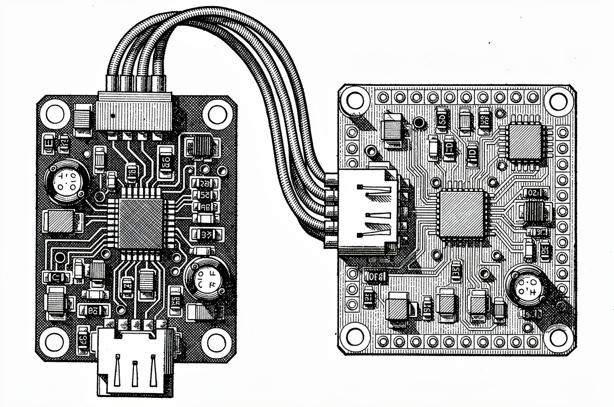
Respuesta rápida: CAN, SMBus y DroneCAN resuelven el mismo problema (sacar la telemetría de la batería fuera del pack) en tres puntos distintos de la curva complejidad-capacidad. SMBus es un enlace simple, con pocos nodos, que convencionalmente se ejecuta en modo maestro único para una batería que dialoga con un host. CAN es un bus multimaestro, tolerante a alta EMI, diseñado para muchos nodos en un solo par de hilos. DroneCAN funciona sobre la capa física de CAN y añade un diccionario de mensajes estandarizado y direccionamiento dinámico de nodos que PX4 y ArduPilot ya hablan de forma nativa. La elección se basa en el número de nodos, la exposición a EMI, y si su pila de vuelo o movimiento ya espera DroneCAN, no en qué protocolo suena más moderno.
Por qué la elección del protocolo condiciona toda la integración del pack
El protocolo de comunicación es una de las últimas cosas que los ingenieros fijan al especificar un pack de baterías personalizado, y una de las más costosas de cambiar después.
Fijarlo tarde hace que tres cosas salgan mal. Primero, la complejidad de pasarela: si el BMS habla SMBus pero el controlador de vuelo solo tiene una interfaz CAN, alguien tiene que construir y validar un puente de protocolo que no habría tenido por qué existir. Segundo, telemetría corrompida por EMI: un bus diseñado para un banco de laboratorio tranquilo se comporta de forma distinta junto a cuatro ESC conmutando a decenas de kilohercios, y esa diferencia se manifiesta como lecturas de tensión intermitentes, no como un fallo limpio. Tercero, comprobaciones de armado previas al vuelo fallidas: la mayoría de las pilas de piloto automático se niegan a armar sin datos de batería válidos y actuales, de modo que una conexión de bus marginal se convierte en una aeronave que no despega, no en un simple hueco de registro.
Nada de esto es mala suerte específica de un protocolo. Es la consecuencia directa de especificar «una interfaz de comunicación» en lugar de especificar CAN, SMBus o DroneCAN con la capa física y el formato de mensaje decididos antes de dibujar la disposición del pack. Esta guía ofrece el detalle a nivel de trama, capa física y modo de fallo para tomar esa decisión correctamente y especificarla de una forma que tanto su proveedor de BMS como su equipo de integración puedan construir.
Los propios packs para drones de Dan-Tech ya se envían de serie con CANBUS, RS485 y UART como opciones de comunicación Smart BMS, y hay variantes de conector compatibles con CAN y DroneCAN disponibles bajo pedido. Este artículo explica lo que realmente ocurre en el cable para que pueda especificar la opción correcta.
CAN, SMBus y DroneCAN comparados: las cifras que importan
Los tres protocolos mueven pequeñas cargas útiles de telemetría (tensión, corriente, temperatura, estado de carga) entre una batería y un host. Difieren en la capa física, el direccionamiento y la topología, no en los datos que transportan.
| CAN (ISO 11898) | SMBus (2.0) | DroneCAN | |
|---|---|---|---|
| Capa física | Par trenzado diferencial (CAN_H/CAN_L) | 2 hilos derivados de I2C (SDA/SCL) + masa | Misma capa física que CAN (funciona sobre CAN 2.0) |
| Velocidad máxima de bits | 1 Mbps en cables cortos, hasta 125 kbps en tramos más largos (una compensación habitual longitud de cable/velocidad de bits en redes CAN de alta velocidad ISO 11898-2, determinada por el presupuesto de tiempo de arbitraje: no es una cifra tabulada literalmente en el texto de la norma) | 100 kHz según la especificación SMBus 2.0; algunas implementaciones de fabricantes toman prestado el modo rápido de 400 kHz de I2C, que no forma parte de la especificación SMBus 2.0 básica | Mismo límite que el bus CAN subyacente, típicamente a 1 Mbps en aplicaciones de drones |
| Arbitraje de bus | Multimaestro, arbitraje bit a bit no destructivo (CSMA/CD+AMP: las colisiones se resuelven, no se evitan) | Maestro único en el uso típico de baterías inteligentes (la especificación derivada de I2C permite técnicamente arbitraje multimaestro, pero las implementaciones de gestión de baterías usan un solo host) | Multimaestro (hereda el arbitraje de CAN) |
| Direccionamiento | ID de arbitraje de 11 o 29 bits por trama, no una dirección de nodo fija | Dirección de dispositivo de 7 bits (112 direcciones utilizables) | ID de nodo de 7 bits (1-127), asignado dinámicamente |
| Longitud de cable práctica | Hasta ~40 m a 1 Mbps, varios cientos de metros a velocidades menores | Aproximadamente 0,5 m en la práctica, determinada por el límite de capacitancia de bus descrito más abajo | Igual que los límites físicos de CAN |
| Número de nodos | No fijado por el protocolo; limitado en la práctica por la capacitancia de entrada del transceptor y la carga del bus a unas pocas decenas de nodos por segmento | Pequeño: SMBus está diseñado para punto a punto o un puñado de dispositivos | Hasta 127 nodos (limitado por el espacio de direcciones de 7 bits del ID de nodo) |
| Conector típico | Específico de la aplicación: JST-GH, Molex Micro-Fit, o un pin de señal dedicado en el conector principal del pack | Conector JST o Micro-Fit pequeño de 2-4 pines junto al conector de potencia | JST-GH de 4 pines (el estándar de facto en PX4/Pixhawk) |
| Soporte nativo en la pila de vuelo | Requiere un controlador; no es en sí mismo un conjunto de mensajes estandarizado único | Habitual en firmware host de «batería inteligente», no nativo en la pila de vuelo | Nativo en PX4 y ArduPilot |
La fila que hace tropezar a la mayoría de las primeras especificaciones es el número de nodos. El propio CAN no limita el número de nodos en un bus; el límite proviene de la capacitancia de entrada del transceptor y la carga del bus, lo cual es una restricción de ingeniería de capa física, no una regla de protocolo. DroneCAN, en cambio, sí tiene un límite estricto: 127 ID de nodo, porque el esquema de direccionamiento tiene un ancho de 7 bits.
Por qué SMBus llega hasta donde llega
El límite de longitud de cable de SMBus no es arbitrario. La especificación SMBus 2.0 limita la capacitancia total del bus a 400 pF. Un cable estándar de dos conductores presenta entre 50 y 100 pF por metro según su construcción, y cada toma de dispositivo y conector añade su propia capacitancia parasita adicional. Al hacer el cálculo, se llega a aproximadamente medio metro de cable practicable antes de que los márgenes de sincronización del bus empiecen a erosionarse y el maestro empiece a ver errores de bits.
Esa es la razón real por la que SMBus es un protocolo «batería a host», no un protocolo «batería a cualquier cosa en la célula aérea». Se diseñó para el dispositivo situado justo al lado de la batería, como el circuito de gestión de energía de un portátil, no para una señal que recorre un larguéro de ala de dos metros hasta el controlador de vuelo. La convención de maestro único usada en los diseños de batería inteligente agrava esto: sin un segundo maestro en el bus contra el que arbitrar, no hay razón para incorporar esa complejidad, por lo que SMBus se mantiene simple por diseño en la práctica, y esa misma simplicidad es exactamente lo que limita su alcance.
Dentro de la trama: cómo es realmente un mensaje de BMS en el cable
Las tablas comparativas le dicen qué protocolo elegir. No le dicen qué hacer una vez que ha elegido CAN o DroneCAN y necesita definir realmente el mensaje que transporta los datos de tensión de celda y temperatura de su BMS. Esta es la parte que todo artículo genérico de visión general de protocolos se salta.
ID de arbitraje CAN, DLC y prioridad
Una trama CAN clásica se construye en torno a tres campos que importan para el diseño del BMS: el ID de arbitraje, el código de longitud de datos (DLC), y la propia carga útil, de hasta 8 bytes.
El ID de arbitraje (11 bits en CAN 2.0A estándar, 29 bits en CAN 2.0B extendido) cumple dos funciones a la vez. Identifica el tipo de mensaje, y fija la prioridad. El arbitraje CAN funciona con bits dominantes: un 0 lógico gana a un 1 lógico cuando dos nodos transmiten al mismo tiempo. Eso significa que un ID numéricamente más bajo gana siempre el arbitraje y se envía primero. Un pack bien diseñado reserva los ID bajos para mensajes críticos de seguridad (subtensión de celda, sobretemperatura, fallo de BMS) y los ID más altos para telemetría rutinaria (estado de carga, número de ciclos), de modo que un mensaje de fallo siempre llega, incluso cuando el bus está ocupado con sondeo rutinario.
El campo DLC indica cuántos bytes de datos siguen, de 0 a 8 en CAN clásico. Una trama de difusión típica de un BMS podría repartir sus 8 bytes así: 2 bytes para la tensión del pack (little-endian, milivoltios), 2 bytes para la corriente del pack (con signo, miliamperios), 1 byte para el estado de carga (0-100 %), 1 byte para la temperatura (codificada con desplazamiento y escala), y 2 bytes para indicadores de estado o un contador cíclico. No existe una norma universal que fije estos desplazamientos de byte exactos. Ese diseño es algo que se define y documenta una vez por proyecto, y es exactamente el tipo de interfaz de comunicación de BMS personalizada que debe especificarse por escrito en una integración de pack, antes de que se escriba el firmware en ambos extremos.
El transporte por byte de cola de DroneCAN
DroneCAN añade una capa de transporte sobre las tramas CAN en bruto para mover mensajes de más de 7 bytes de carga útil (DroneCAN reserva el octavo byte de cada trama para su propio uso, descrito a continuación).
Cada trama CAN de DroneCAN termina en un byte de cola con cuatro campos empaquetados en un solo byte: un indicador de inicio de transferencia, un indicador de fin de transferencia, un bit de conmutación, y un ID de transferencia de 5 bits. Un mensaje que cabe en 7 bytes o menos sale como una única trama con los indicadores de inicio y fin activados. Un mensaje más grande, como un informe completo de estado de batería con campos de tensión, corriente, temperatura y estado de salud juntos, se divide en varias tramas: la primera trama activa el indicador de inicio, la última el de fin, y el bit de conmutación se invierte en cada trama intermedia, de modo que el receptor puede detectar una trama perdida o duplicada en la secuencia.
El direccionamiento de nodos también funciona de forma distinta. En lugar de que cada nodo tenga una dirección fija y preconfigurada, los nodos DroneCAN sin ID asignado transmiten una solicitud de asignación anónima, y un nodo coordinador (o, en una configuración con un único coordinador, el propio controlador de vuelo) les asigna un ID de nodo de 1 a 127. Esto es lo que permite conectar una batería compatible con DroneCAN en una aeronave desconocida y que aparezca sin configurar manualmente una dirección, a costa de ese límite fijo de 127 nodos.
Ejemplo resuelto: decodificar un mensaje BatteryInfo de principio a fin
Repasemos qué ocurre cuando un BMS compatible con DroneCAN informa de su estado. Conceptualmente:
- El BMS ensambla un mensaje de estado de batería: tensión, corriente, porcentaje de capacidad restante, temperatura, y un campo de estado/salud. Esa carga útil supera los 7 bytes.
- La pila DroneCAN del BMS divide la carga útil en bloques secuenciales de 7 bytes y añade un byte de cola a cada uno, compartiendo un mismo ID de transferencia entre todos los bloques de esta transmisión.
- La primera trama CAN sale con el bit de inicio de transferencia del byte de cola activado. Su ID de arbitraje codifica el tipo de mensaje y el propio ID de nodo del BMS, de modo que cualquier nodo que escuche (controlador de vuelo, puente de estación terrestre, registrador) sabe a qué se enfrenta incluso antes de leer la carga útil.
- Las tramas siguientes transportan los bloques de carga útil restantes, cada una con el bit de conmutación invertido respecto a la trama anterior. Si el receptor ve dos tramas consecutivas con el mismo estado de conmutación, sabe que se perdió una trama y descarta el mensaje parcial en lugar de ensamblar datos corruptos.
- La trama final activa el bit de fin de transferencia. El receptor concatena todos los bloques de carga útil en orden y decodifica la estructura completa del estado de la batería.
- Si el controlador de vuelo aún no reconoce el ID de nodo del BMS, todo este intercambio va precedido por el protocolo de asignación dinámica descrito anteriormente.
La conclusión técnica: el byte de cola de DroneCAN convierte un bus limitado a tramas de 8 bytes en uno capaz de transportar mensajes estructurados de tamaño arbitrario, a costa de un byte de carga útil por trama y de la complejidad añadida de la lógica de reensamblaje en ambos extremos.
Capa física y EMI: qué destruye realmente la integridad de la señal CAN en un chasis de dron o robótico
Esta es la sección que todo artículo de la competencia se salta, y suele ser justo donde un bus que funcionaba perfectamente en el banco empieza a perder tramas en vuelo.
La señalización diferencial de CAN es genuinamente robusta frente al ruido de modo común; ese es todo el sentido de usar dos hilos en lugar de uno referenciado a masa. Pero robusto no significa inmune, y un chasis de dron o robótico tiene tres fuentes de ruido que un montaje de banco no tiene: conmutación de ESC/controladores de motor a decenas de kilohercios, picos de corriente de alto di/dt en el cableado de potencia, y retornos de masa compartidos entre las rutas de potencia y de señal.
Terminación. Un bus CAN necesita una resistencia de 120 ohmios en cada extremo físico del bus, dando una impedancia de terminación diferencial combinada de unos 60 ohmios. Una terminación ausente o mal colocada provoca reflexiones de señal que se leen como errores de bits intermitentes, no como un fallo limpio, lo que convierte esto en uno de los problemas de CAN más difíciles de diagnosticar sin un osciloscopio en el bus.
Topología. CAN está diseñado como un bus lineal con ramificaciones cortas, no como una estrella. Las ramificaciones largas desde el tronco principal actúan como antenas sin terminar y reflejan energía de señal de vuelta al bus. Mantenga la longitud de las ramificaciones corta (unos pocos centímetros, no decenas) donde quiera que un nodo se conecte al tronco principal.
Elección de cable y conector. El par trenzado no es opcional; es lo que en primer lugar hace que la señalización diferencial funcione frente al ruido de modo común. Los conectores JST-GH y Molex Micro-Fit son habituales en aeronaves de drones más pequeñas, donde el espacio en la placa es reducido; el XT30 aparece más en plataformas robóticas, donde el conector también debe sobrevivir a vibraciones y ciclos de acoplamiento repetidos. Elija el que elija, mantenga la torsión del par CAN intacta hasta los pines; deshacer la torsión en el conector para ahorrar espacio anula el sentido de usarla.
Retornos de masa compartidos. El mayor error de EMI, con diferencia, en un chasis de dron o robótico consiste en enrutar la referencia de masa de CAN por la misma vía de retorno que la corriente de fase del motor. Cada amperio de corriente de conmutación a través de una masa compartida crea una caída de tensión que se manifiesta como ruido de modo común en el par CAN. Mitíguelo dando a CAN (y a cualquier otro bus de señal de bajo nivel) su propio retorno de masa hacia un punto único, separado de la vía de retorno de alta corriente del motor y el ESC, y manteniendo el par trenzado CAN físicamente alejado de los cables de fase del motor y de los nodos de conmutación del ESC, en lugar de agruparlo con ellos en el mismo mazo.
En el análisis competitivo de Dan-Tech sobre los contenidos mejor posicionados en este tema, ninguno de los artículos cuantifica valores de terminación, límites de longitud de ramificación, o la separación del retorno de masa. Esa es la brecha: las tablas comparativas le dicen qué protocolo elegir, pero no cómo tenderlo para que sobreviva a la aeronave en la que está integrado.
Cuando el bus falla: estados de error, watchdogs, y degradación controlada
Una comparación de protocolos que se detiene en «CAN es más robusto» sin explicar qué ocurre cuando falla no le da lo suficiente para diseñar un sistema seguro a su alrededor.
El mecanismo de conteo de errores de CAN. Cada controlador CAN mantiene un contador de errores de transmisión (TEC) y un contador de errores de recepción (REC). Un error de bus detectado incrementa el contador correspondiente; una transmisión o recepción limpia lo decrementa. Al superar 127 en cualquiera de los contadores, el nodo entra en estado Error Passive, donde aún puede recibir con normalidad pero pierde parte de su capacidad para imponer bits dominantes durante el arbitraje. Al superar 255, el nodo pasa por completo a Bus-Off, desconectándose del bus para proteger al resto de la red de un transmisor posiblemente defectuoso. La recuperación desde Bus-Off requiere, según la implementación, bien una secuencia de recuperación definida (128 apariciones observadas en el bus de 11 bits recesivos consecutivos), bien un reinicio del controlador.
Esto importa para el diseño del pack porque un BMS que entra en Bus-Off debido a un conector ruidoso, no a un fallo real del pack, deja de informar por completo. Si la lógica de seguridad del controlador de vuelo o movimiento no puede distinguir «la batería está bien, la conexión del bus está degradada» de «la batería ha fallado», tomará la decisión equivocada justo en la situación en la que más importa acertar.
Patrones de latido y watchdog. Los nodos DroneCAN transmiten un mensaje periódico de estado/latido (aproximadamente una vez por segundo en implementaciones típicas) específicamente para que un oyente pueda detectar un nodo colgado incluso cuando técnicamente no se ha producido ninguna condición de error. Si el controlador de vuelo deja de ver ese latido dentro de un tiempo de espera definido, trata el nodo como fallido, no simplemente silencioso. SMBus no tiene un latido nativo equivalente; un host que sondea una batería SMBus tiene que definir su propia política de tiempo de espera de lectura y reintento, porque un bus silencioso y un bus ocupado se ven idénticos sin ella.
Degradación controlada. La respuesta correcta ante datos de batería obsoletos es un tiempo de caducidad, no una espera indefinida de la siguiente lectura buena. Si la telemetría CAN o DroneCAN no se ha actualizado dentro de una ventana definida, el controlador debería marcar el estado de la batería como desconocido en lugar de seguir confiando en el último valor, y esa marca debería alimentar la misma lógica de seguridad (advertencia, retorno al punto de despegue, apagado controlado) que activaría un evento real de subtensión. Para SMBus, el equivalente es un número acotado de intentos de lectura fallidos antes de que se active el mismo mecanismo de respaldo. En cualquier caso, el modo de fallo contra el que hay que diseñar es un controlador que sigue volando o conduciendo con datos en los que ya no debería confiar.
Elegir el protocolo: un marco de decisión para la integración OEM
Sáltese el «depende» y trabaje en su lugar cuatro variables concretas.
Número de nodos. Una batería, un host, nada más en el bus: SMBus es genuinamente más simple de implementar y depurar, y no hay razón para cargar con la complejidad adicional de CAN para un enlace que nunca la necesitará. Más de un puñado de dispositivos compartiendo un bus (BMS, ESC, GPS, sensores periféricos): ese es territorio de CAN o DroneCAN, no de SMBus.
Tasa de actualización requerida. La velocidad de bits de clase 100 kHz de SMBus es más que suficiente para una batería que informa una o dos veces por segundo. Si su aplicación necesita actualizaciones de telemetría por debajo de 100 ms en varios nodos que comparten ancho de banda, la mayor velocidad de bits de CAN y su arbitraje multimaestro gestionan la contención del bus mucho mejor de lo que jamás podrá un enlace SMBus de maestro único.
Exposición a EMI. Una batería alojada en una carcasa blindada junto a un único host de baja potencia es un entorno de baja EMI, donde la capa física más simple de SMBus es un compromiso razonable. Un pack cableado a lo largo de una aeronave o chasis junto a controladores de motor es un entorno de alta EMI, donde la señalización diferencial de CAN y la disciplina de capa física descrita anteriormente son la inversión correcta.
Pila de vuelo o movimiento. Si la plataforma funciona con PX4 o ArduPilot, DroneCAN le proporciona soporte nativo y un diccionario de mensajes estandarizado sin escribir un controlador personalizado en el lado del piloto automático, lo cual supone un ahorro real de tiempo de integración. Si la plataforma funciona con una pila de controlador de vuelo o movimiento propietaria, CAN en bruto con una disposición de trama definida a medida (según el diseño de ID de arbitraje y DLC descrito anteriormente) le da control total sobre el formato del mensaje sin heredar el límite de ID de nodo ni la sobrecarga de transporte de DroneCAN.
Topologías CAN multi-BMS y de packs en paralelo para plataformas industriales y robóticas más grandes
Las plataformas industriales y robóticas de mayor tamaño operan cada vez más con múltiples packs de baterías en paralelo, cada uno con su propio BMS, compartiendo un solo bus CAN hacia un controlador central. Este es un escenario realmente relevante para Dan-Tech en el diseño de packs personalizados, y es una brecha en los contenidos mejor posicionados sobre este tema que el análisis competitivo de Dan-Tech identificó.
El problema central de diseño es la colisión de ID de arbitraje. Si cada BMS en un bus multi-pack intenta usar el mismo ID de arbitraje para «tensión de pack», el bus no tiene forma de distinguir de qué pack acaba de llegar la lectura. La solución es una convención de asignación de ID diseñada para ello: reserve un bloque de ID por tipo de mensaje, y luego use un subcampo dentro de ese bloque (o los bits de menor peso de la trama) para transportar un número de instancia de pack, de modo que el mensaje de tensión del pack 1 y el del pack 4 ocupen ID de arbitraje distintos y ordenados de forma determinista. Los mensajes críticos de seguridad (el fallo o la subtensión de cualquier pack individual) siguen recibiendo los ID más bajos en todo el esquema, de modo que el fallo de un pack llega al controlador antes que la telemetría rutinaria de cualquier otro pack en el bus, sin importar qué pack lo informe.
DroneCAN evita parte de este problema por diseño: su servicio de asignación dinámica de ID de nodo ya asigna a cada BMS un ID de nodo único (1-127) sin que un humano tenga que diseñar una convención de numeración. La contrapartida es el mismo límite de 127 nodos comentado anteriormente, que rara vez es una restricción real para una plataforma industrial multi-pack, pero que vale la pena confirmar frente a su número real de nodos (unidades BMS más cualquier otro dispositivo DroneCAN) antes de comprometerse con el protocolo a gran escala.
Decisiones clave: resumen
- SMBus es la elección correcta para una única batería que dialoga con un único host cercano, y su límite práctico de longitud de cable de unos 0,5 m proviene directamente del límite de capacitancia de bus de 400 pF de la especificación SMBus 2.0, no de una decisión de diseño arbitraria.
- CAN es la elección correcta siempre que más de un puñado de nodos compartan un bus, la exposición a EMI sea real, o esté definiendo un formato de mensaje personalizado para una pila de vuelo o movimiento propietaria. El ID de arbitraje actúa también como prioridad de mensaje: los ID numéricamente más bajos siempre ganan.
- DroneCAN es la elección correcta cuando la plataforma ya funciona con PX4 o ArduPilot, proporcionando soporte nativo y un diccionario de mensajes estandarizado. Su transporte por byte de cola permite que los mensajes multitrama superen el límite de 8 bytes por trama de CAN, y su asignación dinámica de ID de nodo elimina la configuración manual de direcciones, a costa de un límite de 127 nodos.
- La disciplina de capa física (terminación de 120 ohmios en cada extremo del bus, ramificaciones cortas, par trenzado mantenido intacto hasta el conector, y un retorno de masa CAN mantenido separado de las vías de corriente del motor/ESC) previene la mayoría de los fallos CAN intermitentes y difíciles de diagnosticar que se observan en chasis de drones y robots.
- Diseñe para una degradación controlada, no solo para la detección: un tiempo de caducidad en la telemetría de la batería, emparejado con la misma lógica de seguridad que activaría un evento real de subtensión, es lo que evita que un fallo de bus se convierta en una decisión de vuelo o movimiento no ordenada.
- Los buses multi-BMS necesitan una convención de asignación de ID diseñada de antemano, antes de que el segundo pack se conecte al bus, no después de que aparezca una colisión de arbitraje en pruebas.
Preguntas frecuentes
¿Es DroneCAN lo mismo que CAN?
No. DroneCAN funciona sobre la misma capa física que el CAN clásico (CAN 2.0), pero añade su propio esquema de direccionamiento, diccionario de mensajes, y protocolo de transporte por byte de cola para mensajes multitrama. Un transceptor CAN es necesario para DroneCAN, pero una trama CAN en bruto sin el byte de cola ni las convenciones de ID de nodo de DroneCAN no es un mensaje DroneCAN válido.
¿Por qué mi bus CAN funciona en el banco pero pierde tramas una vez instalado en la aeronave?
La causa más común es el acoplamiento de EMI a través de un retorno de masa compartido con la corriente de conmutación del motor o el ESC, seguida de una terminación de 120 ohmios ausente o incorrecta y ramificaciones largas sin terminar. Los montajes de banco rara vez presentan alguno de estos tres problemas; las aeronaves instaladas casi siempre, a menos que el mazo se haya tendido específicamente para evitarlos.
¿Cuántos nodos puedo poner en un bus CAN?
El propio CAN no fija un límite estricto de nodos; la restricción real es la capacitancia de entrada del transceptor y la carga total del bus, lo cual en la práctica limita la mayoría de los diseños de bus CAN embebidos a unas pocas decenas de nodos por segmento. DroneCAN añade su propio límite independiente: un tope de 127 nodos derivado de su campo de ID de nodo de 7 bits.
¿Puedo usar SMBus para un bus de telemetría multinodo a lo largo de una aeronave de dron?
No de forma fiable. El uso convencional de maestro único de SMBus y su límite práctico de longitud de cable de aproximadamente 0,5 metros (determinado por su límite de capacitancia de bus de 400 pF) lo hacen adecuado para un enlace batería-a-host, no para un bus compartido por múltiples dispositivos repartidos por una aeronave o chasis.
¿Qué ocurre si un nodo BMS de mi bus CAN entra en Bus-Off?
El nodo deja de transmitir por completo para proteger al resto del bus de un transmisor posiblemente defectuoso, en base a que su contador de errores de transmisión supera 255. La recuperación requiere bien una secuencia de recuperación de bus inactivo definida, bien un reinicio del controlador. Diseñe su lógica de seguridad para tratar un latido ausente o telemetría obsoleta como «estado desconocido», no como «la batería está bien», de modo que un fallo de bus no se confunda con una lectura limpia.
¿Especificando una interfaz de comunicación para un pack de baterías personalizado? Dan-Tech Energy, fabricante de packs de baterías Li-ion personalizados con producción en Alemania y Estados Unidos, integra bajo pedido variantes de conector compatibles con CAN, SMBus y DroneCAN en packs para drones y robótica. Empiece a definir sus requisitos en la ToolBox, o explore el catálogo completo de packs de baterías de iones de litio para ver opciones de celdas y configuración.
Lectura relacionada:
- BMS personalizado para packs de baterías de drones: qué especificar y por qué importa: la decisión PCM frente a BMS, un nivel por encima del detalle de protocolo de este artículo.
- Cómo especificar un pack de baterías UAV personalizado: una guía para fabricantes OEM de drones: el proceso completo de especificación de packs, del que la interfaz de comunicación es un solo elemento.

.png)


